|
|
Operating
Voltage
|
10 -
30 V DC
|
|
Hysteresis
|
Less
than 10 %
|
|
Max.
Switch Rate
|
1.5
KHz ( M12/M18 ) ; 2K Hz ( S17/S18 ) ; 500 Hz ( PB )
|
|
Power-On
Reset Time
|
20 ms
|
|
Circuit
Protection
|
(a)
output short circuit & (b) reverse polarity of supply voltage
|
|
Max.
Load cirrent
|
100 mA
|
|
Sealing
|
Conforming
to IP67
|
|
Cable
Length
|
2
meter, oil retardent, grey color
|
|
Writing
Diagram
|
Brown,
black and blue as standard
|
|
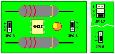
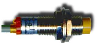 Proximity switch
a. JP XA JP
XA ( Short 2,3 )
b. JP XB JP XB ( Short 1,2 )
| JP0B to JP7B are used to select isolated or non-isolated.
When JPXB-1, JPXB-2 is short, then the corresponds channel is in
isolator mode, When JPXB-2, JPXB-3 is short, the 1XL is short with
system Gnd. So the external signal is in non-isolated mode. JP0A to
JP7A are used to select power signal input or non-power signal input
for the correspond channel. JPXA-1 and JPXA-2 short is power signal
input mode. JPXA-2, JPXA-3 short is non-power input mode. |
c. JP17 ( Short 1,3 )
| JP17 is used to select internal or external power supply
of input channels. When JP17-1 is shorted, the PC bus +12V power is
selected. When JP17-2 is shorted, the PC bus +5V power is selected.
If we short JP17-3, then the external power supplier is selected. |
d. JP18 ( Short 1,2 )
JP18 is to select external or PC bus power supply. JP18-1,
JP18-2 short mean PC bus power, JP18-2, JP18-3 short mean external
power. Suppose you connect more than two 8 channel relay output /
isolator input boards, we suggest you use external power.
|
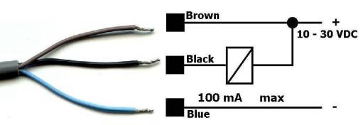
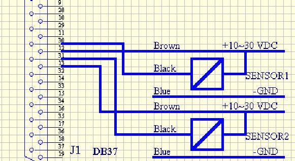
2. Sensors Line
a. Brown
Connect to +12V ( Vcc ) & I10H ( 8 Photo Isolator / 8 Relay
Board)
b. Black Connect to I10L (8 Photo Isolator / 8 Relay Board )
c. Blue Connect to Ground ( Gnd )
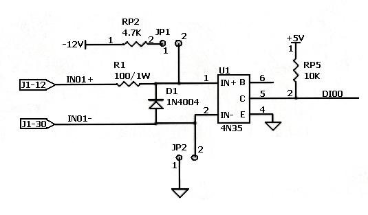
3. Text's Line
4 . Circuit
5. DB37 Connector Ping Assignments
Pin
|
Description
|
1
|
Relay channel 1, NO
|
2
|
Relay channel 1, COM
|
3
|
Relay channel 1, NC
|
4
|
Relay channel 2, NO
|
5
|
Relay channel 2, COM
|
6
|
Relay channel 2, NC
|
7
|
Relay channel 3, NO
|
8
|
Relay channel 3, COM
|
9
|
Relay channel 3, NC
|
10
|
Relay channel 8, NO
|
11
|
Relay channel 8, COM
|
12
|
Opto channel 1, +
|
13
|
Opto
channel 2, +
|
14
|
Opto
channel 3, +
|
15
|
Opto
channel 4, +
|
16
|
Opto
channel 5, +
|
17
|
Opto
channel 6, +
|
18
|
Opto
channel 7, +
|
19
|
Opto
channel 8, +
|
20
|
Relay
channel 4, NO
|
21
|
Relay
channel 4, COM
|
22
|
Relay
channel 4, NC
|
23
|
Relay
channel 5, NO
|
24
|
Relay
channel 5, COM
|
25
|
Relay
channel 6, NO
|
26
|
Relay
channel 6, COM
|
27
|
Relay
channel 7, NO
|
28
|
Relay
channel 7, COM
|
29
|
GND
|
30
|
Opto
channel 1, -
|
31
|
Opto
channel 2, -
|
32
|
Opto
channel 3, -
|
33
|
Opto
channel 4, -
|
34
|
Opto
channel 5, -
|
35
|
Opto
channel 6, -
|
36
|
Opto
channel 7, -
|
37
|
Opto
channel 8, -
|
|
|
|
|