| 412-37 |
Install and Test ISA INDUSTRIAL CONTROL CARD on Linux
This page describes you how to install and test ISA INDUSTRIAL CONTROL Card on linux.
1. Install device driver
1. Instal1 Device driver
This sample is under REDHAT 8.0 KERNEL 2.4.18-14.
1.1 Download device driver
Download the driver you need from as follows:
disaindust_2.2.14.tgz for KERNEL 2.2.14 Release Date:2003/3/05
disaindust_2.4.18.tgz for KERNEL 2.4.18 Release Date:2003/3/05
Download the driver to /
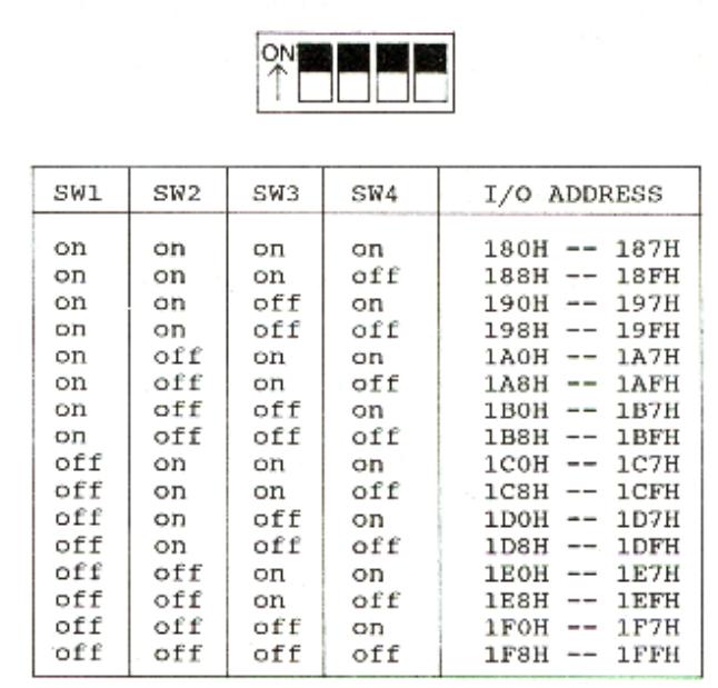
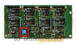
1.2 DIP switch set
DIP switch is used to set I/O address, the I/O address mapping are:
1.3 Instal1 step
To install device driver , perform the following steps:
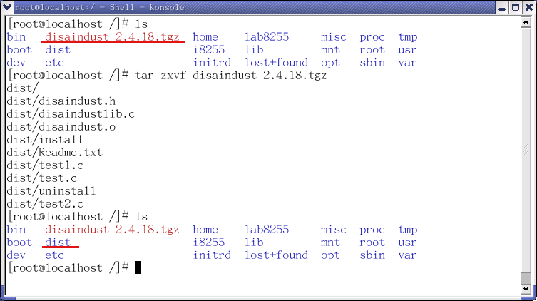
Step1: Extract the file
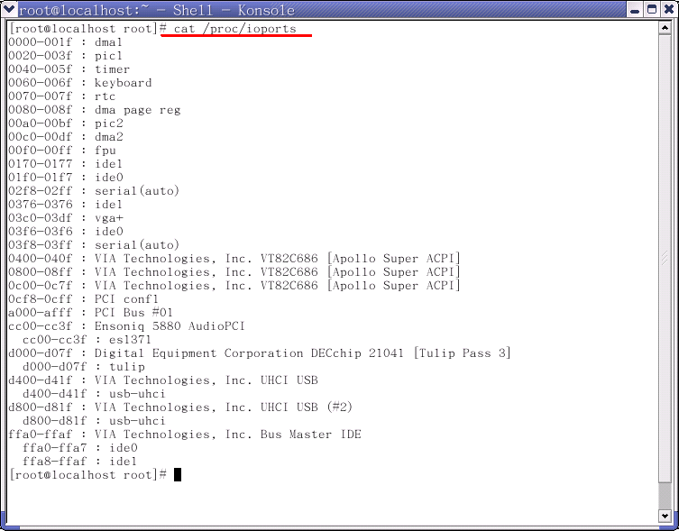
Step 2: Check IO address
You can use ' cat /proc/ioports ' to check which IO address can be used.You can find that H300 and H360 IO
addresses are not be used.
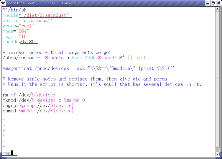
Step 3: Edit /dist/install
Here you need to modify the "install" file,because we should tell driver what the IO address that
card uses.The line that you need to modify is "ioaddr=0x180".It means that the carduse 0x180 as
its IO address.
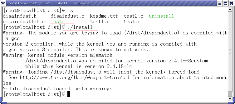
Step 4: Execute the install file to install
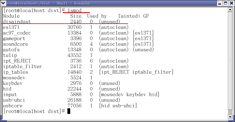
Step 5: Please use "lsmod" command to check
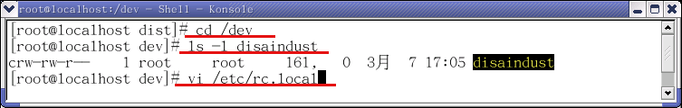
Step 6: Please edit /etc/rc.local to add a command line as follows:
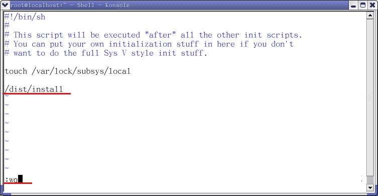
Step 7: Please reboot systems.
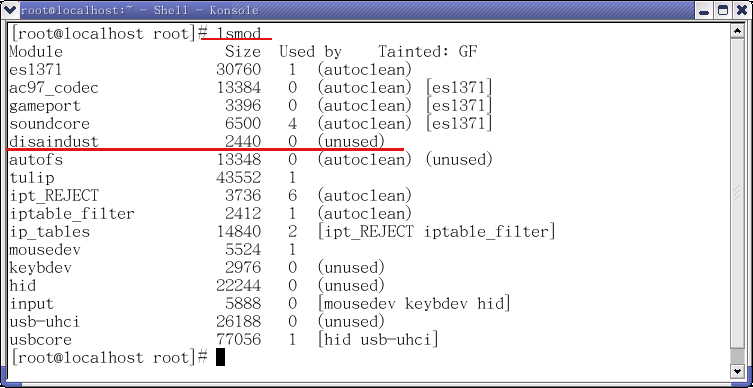
Step 8: Please use 'lsmod' to check after system restarted. You can find 'disaindust' card .
If you do not find the device, please check ' /etc/rc.local ' file .
2. Uninstall the driver
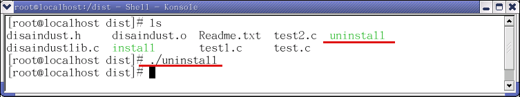
If you want to remove the driver.You can use 'ls' command to find 'uninstall' file.
Then execute the file.
3. Self test the card
3.1 The test tool
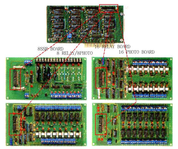
You can use the 8 relay/ 8 photo board, 8 SSR/ 8 logic board, 16 relay board or 16 photo board to test.
3.2 The test programs
The
device driver already includes three test programs.
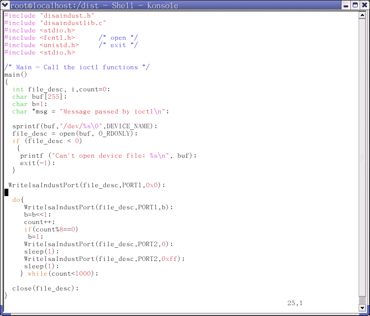
1.test.c: It is the basic I/O program for RELAY OUTPUT.
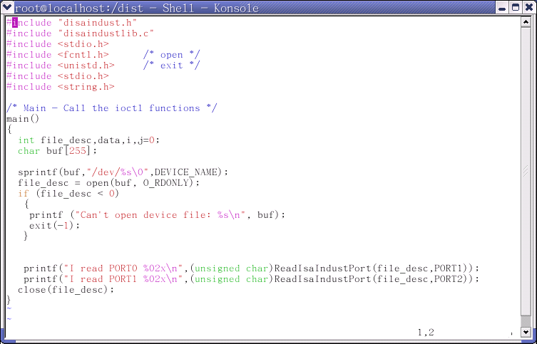
2.test1.c: It is used for test the PHOTO INPUT.
3.test2.c: Manuly tests RELAY OUTPUT.
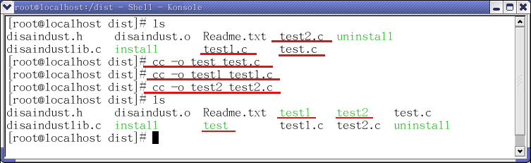
3.2.1 Compile the test files
Please
compile the 'test.c' 'test1.c' 'test2.c' files as following step:
Then it will create the 'test' 'test1' 'test2' file.
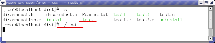
3.2.2 Execute the test file
Please execute the 'test' file to test output. You will see Led light of port0 from L1 to L8 auto ON and OFF
and Led lights of port1 are turned auto ON and auto OFF togegher.
The result:
On 16 relay board : You will see Led light of port0 from L1 to L8 auto ON and OFF and Led lights of port1
are turned auto ON and auto OFF togegher.
On 8 relay/ 8 photo board : You will see Led lights of port1 are turned auto ON and auto OFF togegher.
On 8 SSR/ 8 logic board : You will see Led light of port0 from L1 to L8 auto ON and OFF and Led lights of port1
are turned auto ON and auto OFF togegher.
The test.c's content is as follows:
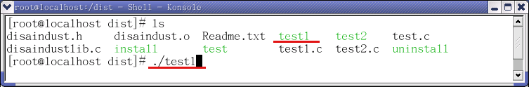
3.2.3 Execute the test1 file
Please execute 'test1' to test the photo input . The result is as follows:
On 16 photo board : Please short J17-2 and j18-2, then you can short U8 to U15 and U19 to U26.
The result will show ' I read from port0 .... ' and ' I read from port1 .... ' .
On 8 8 relay/ 8 photo board : Please short J17-2 , then you can short U9 to U16.
The result will show ' I read from port0 .... ' and ' I read from port1 ff ' .
The test1.c's content is as follows:
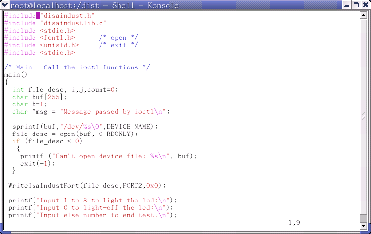
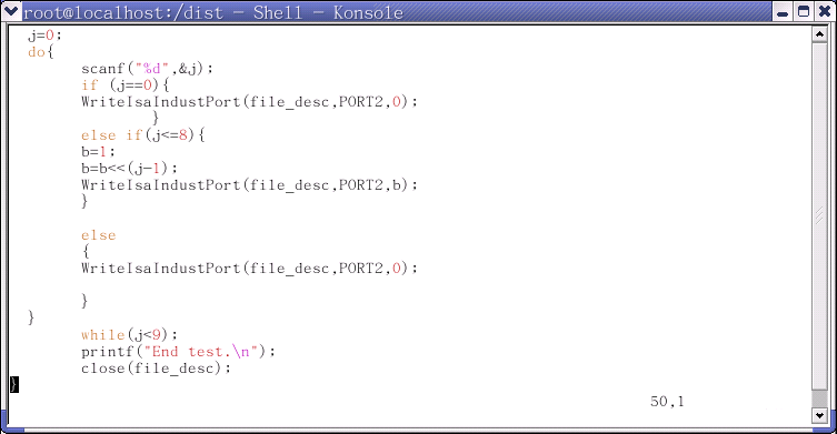
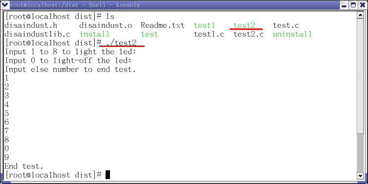
3.2.4 Execute the test2 file
Please execute 'test2' to manuly test output. Use 8 relay/ 8 photo board, 8 SSR/ 8 logic board or 16 relay
board to test. The result is as follows:
The test2.c's content is as follows: