
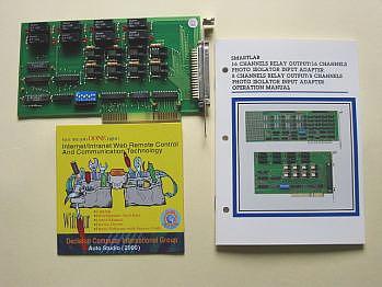
8 channels relay output /photo isolator input card
Product Code: AVRO8B
The 8 channels relay output / photo isolator input adapter provides relay output functions. The relay output part provides 8 relays to drive 8 different output channels. Each relay channel can be used to control ON/ OFF of external devices, to drive external high power relays, to activate alarms Ketc.
The photo
isolator input part provides 8 photo couple digital input channels,
which allow the input signals to be completely floated and
prevent the ground loop.
The features of 8 channels relay output / 8 channels photo isolator input adapter are:
Support 8 relay output channels and 8 photo couple input channels
1. Support 8
relay output channels and 8 photo couple input channels.
2. Max contact rating for relay: 120V / DC 1AMP.
3. Attraction time for relay: 3 ms.
4. Fall off time for relay: 2 ms.
5. Isolation resistance for relay: 100M OHM.
6. Life expectancy for relay: 100 million operation at signal level
load.
7. Allow the photo input signals to be completely floated and
prevent the ground loops.
8. Activation voltage: 17 to 28V or TTL level.
9. Address selectable.
The package includes following item
1. 8
channels relay output / 8 channels photo couple input adapter.
2. User's manual.
 |
HARDWARE INSTALLATION
Your 8 channels relay output / 8 channels photo couple input adapter is designed to inserted in any available slot in designed to inserted in any available slot in your computer. In order to gain access to the expansion slots, follow the steps listed in the followings.
1.Set the
switch and jumper.
2.Connect the expansion cable to DB37 connector.
3.Turn off all power of your computer and all peripheral devices
before installing your adapter.
4.Remove the cover of the computer.
5.Insert your prefigured adapter into any available slot. Make sure
your I/O card is firmly seated in the
 chosen slot.
6.Replace the cover of the computer.
HARDWARE CONFIGURATION
Before you use the 8 channels relay output / 8 channels photo couple input adapter, you must ensure that the I/O address is set correctly, and set IRQ that you needs. Observe the figure in the follows, the proper settings for the 8 channel s relay output / 8 channels photo couple input adapter is described in the following.
2.1 Switch and Jumper Settings
1. I/O Address
DIP switch is used to set base I/O address, you may set I/O address ranges from 200H to 3FEH increments of 2. Observe figure above, to set the switch ON means 0 and set the switch OFF means 1. A9 is always set to 1, SW1 corresponds to address A7, SW2 corresponds to address A7, etc. The figure above is set to 2A8H.
Base Address + 0 :
Relay output channel 1to 8.
Base Address + 1 :
Photo input
channel 1 to 8.
2. Jumper
Setting
|
Jumper A |
Jumper B | Signal |
| left | right | Opto +, opto V |
| left | left | Opto +, GND |
| right | --- | Opto + = TTL mode |
The jumper A and jumper B are used to set isolate signal of photo input. When set left position of jumper A and right position of Jumper B, the photo inputs are isolated, and you must use opto + and opto signals. When set left position of jumper A and left position of jumper B, opto is connected to ground (GND), you only use opto + signal. When set right position of jumper B, the opto + signal accepts TTl level.
2.2 Function Description
1. Relay output
(Base address + 0) is used to control channel 1 to 8. When set the correspond bit to 1, it turns on the relay, this means relay is set to close state, when set the correspond bit to 0, it turns off the relay, this means relay is set to open state.
2. Photo Couple input
(Base address + 1) is used to control channel 1 to 8, bit 0 to bit 7 represents input channel 1 to channel 8. Normally, when input voltage range from 17V to 28V, it means 1, otherwise below 17V is 0. When set to TTL mode, the corresponding bit will be set to 0 or 1 according to TTl level.
|
Pin
|
Description
|
Pin
|
Description
|
|
1
|
Relay channel 1, NO
|
20
|
Relay channel 4, NO
|
|
2
|
Relay channel 1, COM
|
21
|
Relay channel 4, COM
|
|
3
|
Relay channel 1, NC
|
22
|
Relay channel 4, NC
|
|
4
|
Relay channel 2, NO
|
23
|
Relay channel 5, NO
|
|
5
|
Relay channel 2, COM
|
24
|
Relay channel 5, COM
|
|
6
|
Relay channel 2, NC
|
25
|
Relay channel 6, NO
|
|
7
|
Relay channel 3, NO
|
26
|
Relay channel 6, COM
|
|
8
|
Relay channel 3, COM
|
27
|
Relay channel 7, NO
|
|
9
|
Relay channel 3, NC
|
28
|
Relay channel 7, COM
|
|
10
|
Relay channel 8, NO
|
29
|
GND
|
|
11
|
Relay channel 8, COM
|
30
|
Opto channel 1, -
|
|
12
|
Opto channel 1, +
|
31
|
Opto channel 2, -
|
|
13
|
Opto channel 2, +
|
32
|
Opto channel 3, -
|
|
14
|
Opto channel 3, +
|
33
|
Opto channel 4, -
|
|
15
|
Opto channel 4, +
|
34
|
Opto channel 5, -
|
|
16
|
Opto channel 5, +
|
35
|
Opto channel 6, -
|
|
17
|
Opto channel 6, +
|
36
|
Opto channel 7, -
|
|
18
|
Opto channel 7, +
|
37
|
Opto channel 8, -
|
|
19
|
Opto channel 8, +
|
|
|
APPENDIX B
ADDRESS SETTING
Isolated input: The digital signal input with isolated protection.
Photo Isolator :
Word File 4N35
Hyper Link
Relay :
Word File BT-12S
Hyper Link
Catalog |
|
| |
Manual |
| |
Device Driver
|
| |
Self Test Software
& Sample Code |
| |
Web Based DAQ
|
| |
Application
|
| |
Q&A |