| 310-2 |
| |
| INDUSTRIAL / SMARTLAB SERIES
MANUAL |
| PCI BUS 16 CHANNELS PHOTO ISOLATOR INPUT/OUTPUT
ADAPTER |
||||||||||||||||||||||||||||||||||
PCI 16 channels relay output / photo isolator input adapter Product Code:APCI 16 PHOTO / RELAY |
||||||||||||||||||||||||||||||||||
| INTRODUCTION | ||||||||||||||||||||||||||||||||||
| The PCI 16
channels relay output / photo isolator input adapter is a 32 bits PCI
bus board with Plug and Play (PnP) features, it is a programmable I/O
interface card for PC/486, Pentium, or compatibles. The PnP features
let hardware configuration for IRQ and I/O address is detected by BIOS
automatically, you don’t need set switch and jumper. The PCI 16 channels relay output / photo isolator input adapter provides relay output functions. The relay output part provides 16 relays to drive 16 different output channels. Each relay channel can be used to control ON/ OFF of external devices, to drive external power relays, to activate alarms... etc. The photo isolator input part provides 16 photo couple digital input channels, which allow the input signals to be completely floated and prevent the ground loop. |
||||||||||||||||||||||||||||||||||
| The features of PCI
16 channels relay output / 16 channels photo isolator input adapter are: |
||||||||||||||||||||||||||||||||||
| · 32 bits PCI bus
with Plug and Play (PnP) features. · Support 16 relay output channels and 16 photo couple input channels. · Max contact rating for relay: 70V/AC, 100V/DC 0.25AMP. · Response time for relay: 1 ms minimum. · Contact resistance for relay: 0.2 OHM maximum. · Support several operating modes that are programmable. · Activation voltage: When short jumpers
(input range from 0 to 20V)
0 to 1.5V inactive 3 to 20V active When open jumpers (input range from 0 to 30V) 0 to 16.6V inactive 18 to 30V active |
||||||||||||||||||||||||||||||||||
|
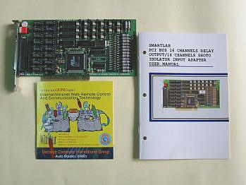
PACKAGE CONTENTS: |
||||||||||||||||||||||||||||||||||
| · SMARTLAB PCI bus 16
channels relay output / 16 channels photo couple input adapter. · User’s manual. · Warranty form. |
||||||||||||||||||||||||||||||||||
|
||||||||||||||||||||||||||||||||||
 |
||||||||||||||||||||||||||||||||||
 |
||||||||||||||||||||||||||||||||||
| HARDWARE
CONFIGURATION |
||||||||||||||||||||||||||||||||||
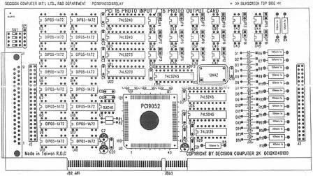
| Before you use the
PCI 16 channels relay output / 16 channels photo couple input adapter,
Please check our technical web site http://www.smatlab.com. Observe the
figure in the follows, the proper settings for the PCI 16 channels
relay
output / 16 channels photo couple input adapter is described in the
following. |
||||||||||||||||||||||||||||||||||
| 2.1 Switch and Jumper
Settings |
||||||||||||||||||||||||||||||||||
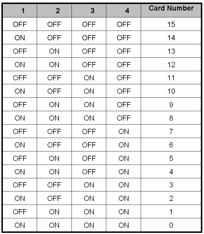
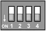
| 1. Card ID
setting |
||||||||||||||||||||||||||||||||||
 |
||||||||||||||||||||||||||||||||||
The switch is used to identify card number, default setting is card 15 , and there are two methods to set the card number: • PnP mode Just plug in SMARTLAB PCI BUS 16 CHANNELS RELAY OUTPUT / 16 CHANNELS PHOTO ISOLATOR INPUT ADAPTER into PCI slot, the PCI BIOS will allocate I/O address to each adapter automatically and assign card number start from 0 to each adapter. You may set any card number at PnP mode, and you need use software tools to distinguish port id. Almost all of the operating systems run at PnP mode. • manual mode Set card number by card identifier switch, the PCI BIOS will assign pre-allocated I/O address to each adapter. Please set different card number to each adapter (do not duplicate card number setting).
• The card number starts from 0 to 15. |
||||||||||||||||||||||||||||||||||
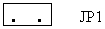
| 2. JP1 to
JP16 |
||||||||||||||||||||||||||||||||||
|
||||||||||||||||||||||||||||||||||
| The JP1 is used to select voltage signal range of photo couple input channel 1, and the JP2 is used to select voltage signal range of photo input channel 2, When we short the jumper, the input voltage range is 0 to 20V, and open the jumper means input voltage range is 0 to 35V. | ||||||||||||||||||||||||||||||||||
| 2.2 I/O Address | ||||||||||||||||||||||||||||||||||
| The PnP feature will get base I/O
address automatically, where Base Address + 0: Relay output channel 1 to 16 |
||||||||||||||||||||||||||||||||||
|
||||||||||||||||||||||||||||||||||
| Base Address + 0: Photo isolator input channel 1 to 16. |
||||||||||||||||||||||||||||||||||
|
||||||||||||||||||||||||||||||||||
| 2.3 Connector
Assignments 1. DB 37 Connector Pin Assignments |
||||||||||||||||||||||||||||||||||
|
||||||||||||||||||||||||||||||||||
| |
||||||||||||||||||||||||||||||||||
| 2.
40 Pins Connector J2 |
||||||||||||||||||||||||||||||||||
|
||||||||||||||||||||||||||||||||||
| |
||||||||||||||||||||||||||||||||||
| 3. 40 Pins Connector
J3 |
||||||||||||||||||||||||||||||||||
|
||||||||||||||||||||||||||||||||||
| |
||||||||||||||||||||||||||||||||||
| DOWNLOAD PCI BUS 16 RELAY OUTPUT/16 PHOTO
ISOLATOR CARD DOC |
||||||||||||||||||||||||||||||||||
|
Technical data - Isolated input Output and Relay
Output Relay : |
||||||||||||||||||||||||||||||||||
|