
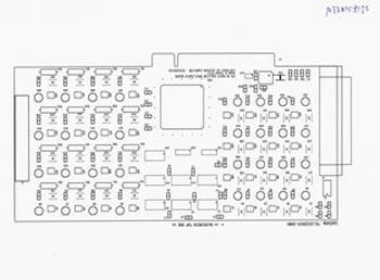
PCI 16 channels photo isolator input / output adapter
Product Code:APCI 16 PHOTO
The PCI 16 channels photo isolator input/output adapter is a 32 bits PCI bus board with Plug and Play (PnP) features, it is a programmable I/O interface card for PC/486, Pentium, or compatibles. The PnP features let hardware configuration for IRQ and I/O address is detected by BIOS automatically, you don't need set switch and jumper.
The PCI 16 channels photo isolator input/output adapter provides 16 photo couple digital input/output channels, which allow the input/output signals to be completely floated and prevent the ground loop.
The features of PCI 16 channels photo isolator input/output adapter are:
* 32 bits PCI bus with Plug and Play (PnP) features.
* Support 16 photo couple input/output channels.
* Allow the photo input/output signals to be completely floated and prevent the ground loops.
* By using 4N33 photo couple chips.
* 1500V isolation voltage.
* Maximum load voltage is 30V.
* Maximum 80mA input current.
* Voltage range from 0V to 30V, where 0 to 3V is OFF and 5V to 30V is ON.
* Operating temperature range from 0 to 33C.
* Relative humidity rage from 0 to 90%.
| * SMARTLAB PCI bus
16 channels photo couple input/output adapter. * User's manual. * Warranty form. |
| 1. |
Turn off all power to
your computer and all peripheral devices before installing your 16
channels photo isolator input/output adapter. |
| 2. |
Remove the cover of
the computer. |
| 3. |
Insert the 16 channels
photo isolator input/output adapter into any available PCI slot. Make
sure the adapter is firmly seated in the chosen slot. |
| 4. |
Replace the cover of
the computer. |
| 5. |
Turn on the power of
your computer, the PnP features will recognize the 16 channels photo
isolator input/output adapter. |
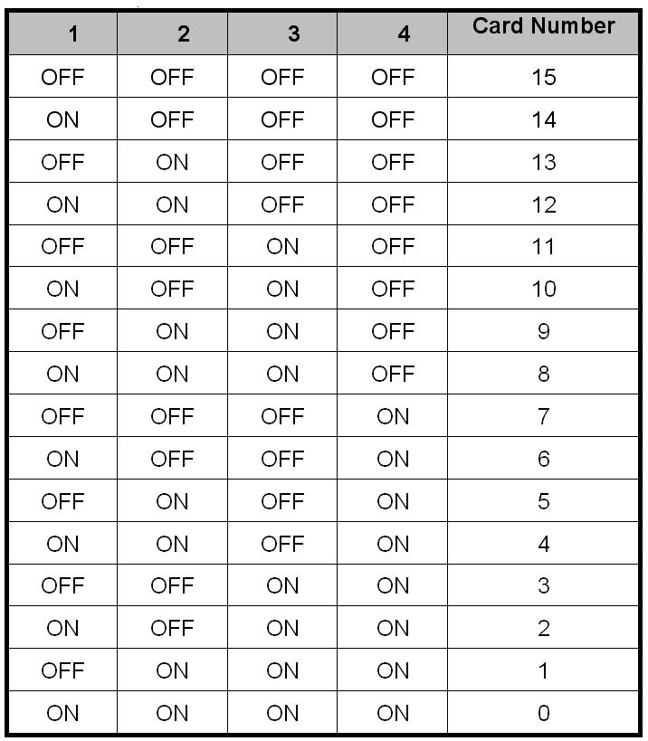
| 3.1 Switch Settings |
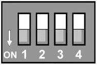 |
The switch is used to identify card number, default setting is card 15 , and there are two methods to set the card number: • PnP mode Just plug in SMARTLAB PCI BUS 16 CHANNELS RELAY OUTPUT / 16 CHANNELS PHOTO ISOLATOR INPUT ADAPTER into PCI slot, the PCI BIOS will allocate I/O address to each adapter automatically and assign card number start from 0 to each adapter. You may set any card number at PnP mode, and you need use software tools to distinguish port id. Almost all of the operating systems run at PnP mode. • manual mode Set card number by card identifier switch, the PCI BIOS will assign pre-allocated I/O address to each adapter. Please set different card number to each adapter (do not duplicate card number setting).
• The card number starts from 0 to 15. |
|||||||||||||||||||||||||||||||||
| 3.2 I/O Address |
|||||||||||||||||||||||||||||||||
| The PnP feature will get
base I/O address automatically, where
Base
Address + 0: |
|||||||||||||||||||||||||||||||||
|
|||||||||||||||||||||||||||||||||
| Base Address + 0: Photo isolator input channel 1 to 16. |
|||||||||||||||||||||||||||||||||
|
3.3 Connector Assignments
| Pin |
Single |
Description |
| 1 |
PAO-01+ | Opto-isolator
Ch. 01 + Output |
| 2 |
PAO -01- | Opto-isolator Ch. 01 - Output |
| 3 |
PAO -02+ | Opto-isolator Ch. 02 + Output |
| 4 |
PAO -02- | Opto-isolator Ch. 02 - Output |
| 5 |
PAO -03+ | Opto-isolator Ch. 03 + Output |
| 6 |
PAO -03- | Opto-isolator Ch. 03 - Output |
| 7 |
PAO -04+ | Opto-isolator Ch. 04 + Output |
| 8 |
PAO -04- | Opto-isolator Ch. 04 - Output |
| 9 |
PAO -05+ | Opto-isolator Ch. 05 + Output |
| 10 |
PAO -05- | Opto-isolator Ch. 05 - Output |
| 11 |
PAO -06+ | Opto-isolator Ch. 06 + Output |
| 12 | PAO
-06- |
Opto-isolator Ch. 06 - Output |
| 13 |
PAO -07+ | Opto-isolator Ch. 07 + Output |
| 14 |
PAO -07- | Opto-isolator Ch. 07 - Output |
| 15 |
PAO -08+ | Opto-isolator Ch. 08 + Output |
| 16 |
PAO -08- | Opto-isolator Ch. 08 - Output |
| 17 |
NC |
|
| 18 |
NC | |
| 19 |
NC | |
| 20 |
PBO-01+ | Opto-isolator
Ch. 09 + Output |
| 21 |
PBO -01- | Opto-isolator Ch. 09 - Output |
| 22 |
PBO-02+ | Opto-isolator Ch. 10 + Output |
| 23 |
PBO -02- | Opto-isolator Ch. 10 - Output |
| 24 |
PBO-03+ | Opto-isolator Ch. 11 + Output |
| 25 |
PBO -03- | Opto-isolator Ch. 11 - Output |
| 26 |
PBO-04+ | Opto-isolator Ch. 12 + Output |
| 27 |
PBO -04- | Opto-isolator Ch. 12 - Output |
| 28 |
PBO-05+ | Opto-isolator Ch. 13 + Output |
| 29 |
PBO -05- | Opto-isolator Ch. 13 - Output |
| 30 |
PBO-06+ | Opto-isolator Ch. 14 + Output |
| 31 |
PBO -06- | Opto-isolator Ch. 14 - Output |
| 32 |
PBO-07+ | Opto-isolator Ch. 15 + Output |
| 33 |
PBO -07- | Opto-isolator Ch. 15 - Output |
| 34 |
PBO-08+ | Opto-isolator Ch. 16 + Output |
| 35 |
PBO -08- | Opto-isolator Ch. 16 - Output |
| 36 |
NC | |
| 37 |
NC |
| Pin |
Single |
Description |
| 1 |
PAO
-01+ |
Opto-isolator
Ch. 01 + Input |
| 3 |
PAO -01- | Opto-isolator Ch. 01 - Input |
| 5 |
PAO -02+ | Opto-isolator Ch. 02 + Input |
| 7 |
PAO -02- | Opto-isolator Ch. 02 - Input |
| 9 |
PAO -03+ | Opto-isolator Ch. 03 + Input |
| 11 |
PAO -03- | Opto-isolator Ch. 03 - Input |
| 13 |
PAO -04+ | Opto-isolator Ch. 04 + Input |
| 15 |
PAO -04- | Opto-isolator Ch. 04 - Input |
| 17 |
PAO -05+ | Opto-isolator Ch. 05 + Input |
| 19 |
PAO -05- | Opto-isolator Ch. 05 - Input |
| 21 |
PAO -06+ | Opto-isolator Ch. 06 + Input |
| 23 |
PAO -06- | Opto-isolator Ch. 06 - Input |
| 25 |
PAO -07+ | Opto-isolator Ch. 07 + Input |
| 27 |
PAO -07- | Opto-isolator Ch. 07 - Input |
| 29 |
PAO -08+ | Opto-isolator Ch. 08 + Input |
| 31 |
PAO -08- | Opto-isolator Ch. 08 - Input |
| 33 |
NC |
|
| 35 |
NC | |
| 37 |
NC | |
| 2 |
PBO -01+ | Opto-isolator Ch. 09 + Input |
| 4 |
PBO
-01- |
Opto-isolator Ch. 09 - Input |
| 6 |
PBO -02+ | Opto-isolator Ch. 10 + Input |
| 8 |
PBO -02- | Opto-isolator Ch. 10 - Input |
| 10 |
PBO -03+ | Opto-isolator Ch. 11 + Input |
| 12 |
PBO -03- | Opto-isolator Ch. 11 - Input |
| 14 |
PBO -04+ | Opto-isolator Ch. 12 + Input |
| 16 |
PBO -04- | Opto-isolator Ch. 12 - Input |
| 18 |
PBO -05+ | Opto-isolator Ch. 13 + Input |
| 20 |
PBO -05- | Opto-isolator Ch. 13 - Input |
| 22 |
PBO -06+ | Opto-isolator Ch. 14 + Input |
| 24 |
PBO -06- | Opto-isolator Ch. 14 - Input |
| 26 |
PBO -07+ | Opto-isolator Ch. 15 + Input |
| 28 |
PBO -07- | Opto-isolator Ch. 15 - Input |
| 30 |
PBO -08+ | Opto-isolator Ch. 16 + Input |
| 32 |
PBO -08- | Opto-isolator Ch. 16 - Input |
| 34 |
NC | |
| 36 |
NC |
| Pin |
Single |
Description |
| 1 |
PAI-01+ |
Opto-isolator
Ch. 01 + Input |
| 3 |
PAI -01- | Opto-isolator Ch. 01 - Input |
| 5 |
PAI-02+ | Opto-isolator Ch. 02 + Input |
| 7 |
PAI -02- | Opto-isolator Ch. 02 - Input |
| 9 |
PAI-03+ | Opto-isolator Ch. 03 + Input |
| 11 |
PAI -03- | Opto-isolator Ch. 03 - Input |
| 13 |
PAI-04+ | Opto-isolator Ch. 04 + Input |
| 15 |
PAI -04- | Opto-isolator Ch. 04 - Input |
| 17 |
PAI-05+ | Opto-isolator Ch. 05 + Input |
| 19 |
PAI -05- | Opto-isolator Ch. 05 - Input |
| 21 |
PAI-06+ | Opto-isolator Ch. 06 + Input |
| 23 |
PAI -06- | Opto-isolator Ch. 06 - Input |
| 25 |
PAI-07+ | Opto-isolator Ch. 07 + Input |
| 27 |
PAI -07- | Opto-isolator Ch. 07 - Input |
| 29 |
PAI-08+ | Opto-isolator Ch. 08 + Input |
| 31 |
PAI -08- | Opto-isolator Ch. 08 - Input |
| 33 |
NC |
|
| 35 |
NC | |
| 37 |
NC | |
| 2 |
NC | |
| 4 |
PBI -01+ | Opto-isolator Ch. 09 + Input |
| 6 |
PBI
-01- |
Opto-isolator Ch. 09 - Input |
| 8 |
PBI -02+ | Opto-isolator Ch. 10 + Input |
| 10 |
PBI -02- | Opto-isolator Ch. 10 - Input |
| 12 |
PBI -03+ | Opto-isolator Ch. 11 + Input |
| 14 |
PBI -03- | Opto-isolator Ch. 11 - Input |
| 16 |
PBI -04+ | Opto-isolator Ch. 12 + Input |
| 18 |
PBI -04- | Opto-isolator Ch. 12 - Input |
| 20 |
PBI -05+ | Opto-isolator Ch. 13 + Input |
| 22 |
PBI -05- | Opto-isolator Ch. 13 - Input |
| 24 |
PBI -06+ | Opto-isolator Ch. 14 + Input |
| 26 |
PBI -06- | Opto-isolator Ch. 14 - Input |
| 28 |
PBI -07+ | Opto-isolator Ch. 15 + Input |
| 30 |
PBI -07- | Opto-isolator Ch. 15 - Input |
| 32 |
PBI -08+ | Opto-isolator Ch. 16 + Input |
| 34 |
PBI -08- | Opto-isolator Ch. 16 - Input |
| 36 |
NC | |
| NC | ||
| NC | ||
| NC |
| Pin |
Single |
Description |
| 1 |
PAI-01+ |
Opto-isolator
Ch. 01 + Input |
| 2 |
PAI -01- | Opto-isolator Ch. 01 - Input |
| 3 |
PAI-02+ | Opto-isolator Ch. 02 + Input |
| 4 |
PAI -02- | Opto-isolator Ch. 02 - Input |
| 5 |
PAI-03+ | Opto-isolator Ch. 03 + Input |
| 6 |
PAI -03- | Opto-isolator Ch. 03 - Input |
| 7 |
PAI-04+ | Opto-isolator Ch. 04 + Input |
| 8 |
PAI -04- | Opto-isolator Ch. 04 - Input |
| 9 |
PAI-05+ | Opto-isolator Ch. 05 + Input |
| 10 |
PAI -05- | Opto-isolator Ch. 05 - Input |
| 11 |
PAI-06+ | Opto-isolator Ch. 06 + Input |
| 12 | PAI -06- | Opto-isolator Ch. 06 - Input |
| 13 |
PAI-07+ | Opto-isolator Ch. 07 + Input |
| 14 |
PAI -07- | Opto-isolator Ch. 07 - Input |
| 15 |
PAI-08+ | Opto-isolator Ch. 08 + Input |
| 16 |
PAI -08- | Opto-isolator Ch. 08 - Input |
| 17 |
NC |
|
| 18 |
NC | |
| 19 |
NC | |
| 20 |
NC | |
| 21 |
PBI -01+ | Opto-isolator Ch. 09 + Input |
| 22 |
PBI
-01- |
Opto-isolator Ch. 09 - Input |
| 23 |
PBI -02+ | Opto-isolator Ch. 10 + Input |
| 24 |
PBI -02- | Opto-isolator Ch. 10 - Input |
| 25 |
PBI -03+ | Opto-isolator Ch. 11 + Input |
| 26 |
PBI -03- | Opto-isolator Ch. 11 - Input |
| 27 |
PBI -04+ | Opto-isolator Ch. 12 + Input |
| 28 |
PBI -04- | Opto-isolator Ch. 12 - Input |
| 29 |
PBI -05+ | Opto-isolator Ch. 13 + Input |
| 30 |
PBI -05- | Opto-isolator Ch. 13 - Input |
| 31 |
PBI -06+ | Opto-isolator Ch. 14 + Input |
| 32 |
PBI -06- | Opto-isolator Ch. 14 - Input |
| 33 |
PBI -07+ | Opto-isolator Ch. 15 + Input |
| 34 |
PBI -07- | Opto-isolator Ch. 15 - Input |
| 35 |
PBI -08+ | Opto-isolator Ch. 16 + Input |
| 36 |
PBI -08- | Opto-isolator Ch. 16 - Input |
| 37 |
NC |
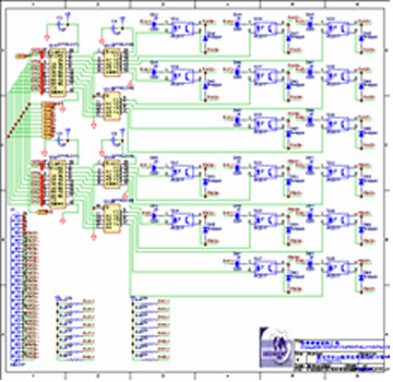
3.4 Loopback Diagnostic
In this experiment, if VCC larger than 10V, then it input HIGH to input channel, otherwise it input LOW; your program can get this digital signal easily. If no VCC voltage input, the output channel will be loopback to input channel, it means when output HIGH then input channel get HIGH, when output LOW then input channel get LOW.
The digital signal input with isolated protection.
Photo Isolator :
PDF File PC817
|
