
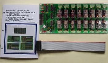
The 16 channel relay/24V output board provides 16 Single Pole Double Throw (SPDT) relays to drive 16 digital output lines. Each relay channel can be used to control ON / OFF of external devices, to drive external high power relays, to activate alarms etc. There are 16 LED indicators correspond to 16 relays, when relay is energized, the corresponding LED is light. The power source is provided from +12V or +24V external power supplier.
The features of 16 Channel Relay/24V Output
Board are:
| 1. |
Support 16 relay output channels. |
| 2. |
LED indicates when relay is energized. |
| 3. |
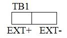
Power is provided from 12VDC or 24VDC external power supplier. |
| 4. |
Built in screw terminals for easy wiring. |
| 5. |
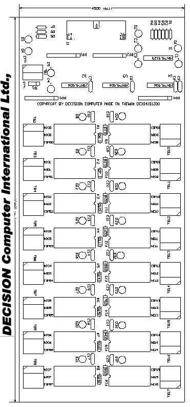
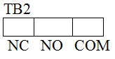
The Normal Open (NO), Normal Close (NC), and Common contacts (COM) of each relay are brought out to the screw connector. |
| 6. |
Max contract rating: 250VAC 10 Amp, 30VDC 10Amp. |
| 7. |
Operate (set) time: 15ms max. |
| 8. |
Release (reset) time: AC 10ms max, DC 5ms max. |
| 9. |
Max Operating voltage 380VAC or 125VDC, and max operating current 10A. |
| 10. |
Max switching capacity 2500VA 300W. |
| 11. |
DC coil 24VDC for 1100 ohm resistance or 12VDC for 275 ohm resistance. |
| |
The package includes following item The package contains: 1.16 channels relay/24V output board. 24VDC coil type or 12VDC coil type. 2.One 26 pins flat cable. 3.User's manual. 4.Warranty form. |
|
|
1. Signal assignment of 26 pins flat cable
|
Pin
|
Description
|
Pin
|
Description
|
|
No. |
|
No.
|
|
|
1
|
+12V
|
14
|
GND
|
|
2
|
GND
|
15
|
GND
|
|
3
|
Line00
|
16
|
Line01
|
|
4
|
Line02
|
17
|
Line03
|
|
5
|
Line04
|
18
|
Line05
|
|
6
|
Line06
|
19
|
Line07
|
|
7
|
Line08
|
20
|
Line09
|
|
8
|
Line10
|
21
|
Line11
|
|
9
|
Line12
|
22
|
Line13
|
|
10
|
Line14
|
23
|
Line15
|
|
11
|
CE
|
24
|
CE
|
|
12
|
+5V
|
25
|
GND
|
|
13
|
-12V
|
26
|
GND
|
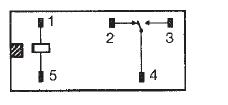
Terminal arrangement/ Internal connections (Bottom view)
|
|
Catalog |
|
| |
Manual |
| |
Device Driver
|
| |
Self Test Software
& Sample Code |
| |
Web Based DAQ
|
| |
Application
|
| |
Q&A |