
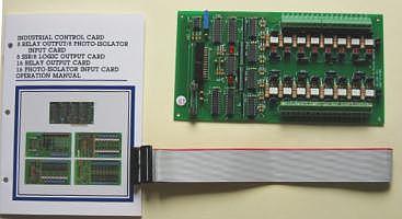
16 Channel Isolator Input Board
Product Code: A16PHOTO
The 16 channel isolator
input board provides 16 opto-isolated digital input channels, which
allow the input signals to be completely floated and
prevent the ground loop. There are 16 LED indicators
correspond to 16 input channels, when the input channel is
activated at high status, the corresponding LED is light.
The power source is user selectable from internal PC bus or external
power supplier.
The features of 16 channel isolator input board are:
| 1. |
Support 16 opto-isolated input channels. |
| 2. |
LED indicates when input channel is activated. |
| 3. |
Internal and external power selectable. |
| 4. |
Built in screw terminals for easy wiring. |
| 5. |
Allow the input signals to be completely floated and
prevent the ground loops. |
| 6. | Isolated or non-isolated modes selectable. |
| 7. |
Input signals are buffered with voltage comparators. |
| 8. |
Input threshold voltage adjustable. |
| 9. |
Breakdown voltage: 1500V VDC. |
| 10. |
Screw terminal: accept #22 to #12 awg wire. |
| 11. |
Input current: 80mA maximum for each isolated input. |
| 12. |
Input voltage: 30VDC maximum for each isolated input. |
| |
The package includes following item The package contains: 1.16 channel isolator input board. 2.One 26 pins flat cable. 3.User's manual. |
|
|
2.1 Configuration For Jumper
Before you use the 16
channel isolator input board, you must
ensure that the power supplier, jumpers, and connectors are set
correctly. Observe the figure in the following, the proper
settings
for the 16 channel isolator input board are described inthe follows.
1. Internal/external power selection

User may use jumpers to select external or internal power supply. When internal power is selected, the PC bus power +12V or +5V can be selected by the user. The external power supplier can be adjusted from +5V to +30V.
JP17 is used to select internal or external power supply of Input channels I10 to I17, and JP18 is used to select internal or external power supply of input channels I20 to I27. When JP17-1 or JP18-1 is shorted, the PC bus +12V power is selected, when JP17-2 or JP18-2 is shorted, the PC bus +5V power is selected. If we short JP17-3 or JP18-3, then the external power supplier is selected.
2. External power supplier
TB1-VEXT+, TB1-VEXT- and TB2-VEXT+, TB2- VEXT- are used to connect external power, the configuration is shown in the follows.
The power supplier of I10 to I17 are TB1, and the power supplier of I20 to I27 are TB2. The external power range is from 5V to 30V.
3. Isolated and Non-isolated
JP0A to JP15A and JP0B to JP15B are used to select isolated or non-isolated, the JPXA corresponding to I1X channel and the JPXB corresponding to I2X channel. When JPXA-1, JPXA-2 is short and JPXB-1, JPXB-2 is sort, then the corresponds channel is in isolator mode. When JPXA-2, JPXA-3 is short and JPXB-2, JPXB-3 is short, the power is supplied by PC bus or external power supplier.
2.2 Signal Assignments
1. Signal assignment of 26 pins flat cable
The 26 pins flat cable connector is connected to digital input interface card such as: industry control, TTL I/O, 8255 I/O, ...etc. The signal assignment of this connector is shown in the following.
2. Signal assignment of screw connector
The signal assignment of each screw connector is shown in the follows.
1. Internal/external power selection
User may use jumpers to select external or internal power supply. When internal power is selected, the PC bus power +12V or +5V can be selected by the user. The external power supplier can be adjusted from +5V to +30V.
JP17 is used to select internal or external power supply of Input channels I10 to I17, and JP18 is used to select internal or external power supply of input channels I20 to I27. When JP17-1 or JP18-1 is shorted, the PC bus +12V power is selected, when JP17-2 or JP18-2 is shorted, the PC bus +5V power is selected. If we short JP17-3 or JP18-3, then the external power supplier is selected.
2. External power supplier
TB1-VEXT+, TB1-VEXT- and TB2-VEXT+, TB2- VEXT- are used to connect external power, the configuration is shown in the follows.
The power supplier of I10 to I17 are TB1, and the power supplier of I20 to I27 are TB2. The external power range is from 5V to 30V.
3. Isolated and Non-isolated
JP0A to JP15A and JP0B to JP15B are used to select isolated or non-isolated, the JPXA corresponding to I1X channel and the JPXB corresponding to I2X channel. When JPXA-1, JPXA-2 is short and JPXB-1, JPXB-2 is sort, then the corresponds channel is in isolator mode. When JPXA-2, JPXA-3 is short and JPXB-2, JPXB-3 is short, the power is supplied by PC bus or external power supplier.
2.2 Signal Assignments
1. Signal assignment of 26 pins flat cable
The 26 pins flat cable connector is connected to digital input interface card such as: industry control, TTL I/O, 8255 I/O, ...etc. The signal assignment of this connector is shown in the following.
| Pin No. |
Specifiaction | Pin No. |
Specifiaction |
| 1 2 3 4 5 6 7 8 9 10 11 12 13 |
+12V
GND +12V GND I10 I11 I12 I13 I14 I15 I16 I17 I20 |
14 15 16 17 18 19 20 21 22 23 24 25 26 |
I21 I22 I23 I24 I25 I26 I27 /CS1 /CS2 +5V GND -12V GND |
2. Signal assignment of screw connector
The signal assignment of each screw connector is shown in the follows.
| No.
|
TB1 | TB2 |
| 1 2 3 4 5 6 7 8 9 10 11 12 13 14 15 16 17 18 |
I10H I10L I11H I11L I12H I12L I13H I13L I14H I14L I15H I15L I16H I16L I17H I17L VEXT+ VEXT- |
I20H I20L I21H I21L I22H I22L I23H I23L I24H I24L I25H I25L I26H I26L I27H I27L VEXT+ VEXT- |
Catalog |
|
| |
Manual |
| |
Device Driver |
| |
Self Test Software
& Sample Code |
| |
Web Based DAQ |
| |
Application
|
| Q&A |