
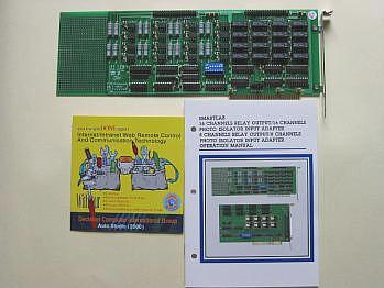
16 channels relay output / photo isolator input adapter
Product Code:A16RELAY / PHOTO
The 16 channels relay output / photo isolator input adapter provides relay output functions. The relay output part provides 16 relays to drive 16 different output channels. Each relay channel can be used to control ON/ OFF of external devices, to drive external high power relays, to activate alarms Ketc.
The photo
isolator input part provides 16 photo couple digital input
channels, which allow the input signals to be completely
floated and prevent the ground loop.
The features of 16 channels relay output / 16 channels photo isolator input adapter are:
Support 16 relay output channels and 16 photo couple input channels
1. Max
contact rating for relay: 150V / DC 1AMP.
2. Response time for relay: 1 ms minimum.
3. Contact resistance for relay: 0.2 OHM maximum.
4. Support several operating modes which are programmable
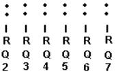
5. Sixteen LED indicate when I/O is operating.
6. Port address selectable.
The package includes following
item
Package
Contains:
16 channels relay
output / 16 channels photo couple input adapter.
User's manual.
 |
HARDWARE INSTALLATION
Your 16 channels relay output / 16 channels photo couple input adapter is designed to inserted in any available slot in your computer. In order to gain access to the expansion slots, follow the steps listed in the followings.
Set the
switch and jumper.
Connect the expansion flat cable to 40 pin connector.
Turn off all power of your computer and all peripheral devices
before installing your adapter.
Remove the cover of the computer.
Insert your reconfigured adapter into any available slot. Make sure
your I/O card is firmly seated in the chosen slot.
Replace the cover of the computer.
HARDWARE CONFIGURATION
Before you use the 16 channels relay output / 16 channels photo couple input adapter, you must ensure that the I/O address is set correctly, and set IRQ that you needs. Observe the figure in the follows, the proper settings for the 16 channel s relay output / 16 channels photo couple input adapter is described in the following.
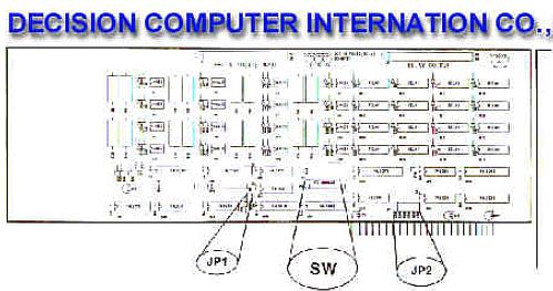
2.1 Switch and Jumper Settings
1. I/O Address
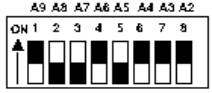
DIP switch is used to set base I/O address, you may set I/O address ranges from 000H to 3FCH increments of 4. Observe figure above, to set the switch ON means 0 and set the switch OFF means 1. SW1 corresponds to address A9, SW2 corresponds to address A8, etc. The figure above is set to 1A0H.
Base Address + 0 :
Relay output channel 1 to 8.
Base Address + 1:
Relay output channel 9 to 16.
Base Address + 0 :
Photo input channel 1 to 8.
Photo Input channel 9 to 16.
2. IRQ Setting
The jumper is used to set IRQ for photo couple input, if you need not to use IRQ, please do not short the jumper
2.3 Function Description
1. Relay
Output
(Base address + 0) is used to control channel 1 to 8, (Base address +
1) is used to control channel 9 to 16. When set the correspond bit
to 1, it turns on the relay, this means relay is set to close
state, when set the correspond bit to 0, it turns off the relay,
this means relay is set to open state.
2. Photo
Couple Input
(Base address + 0) is used to control channel 1 to 8, (Base address +
1) is used to control channel 9 to 16. When input voltage range
from 0 to 2 VDC, then input circuit turns off and its correspond
bit will set to 0, when input voltage range from 3 to 45 VDC, then
input circuit turns on and its correspond bit will be set to 1. Do
not input signal more than 50 VDC, otherwise the circuit will
overload.
1. Connector 1 (J1)
|
Pin
|
Description
|
|
1,2
|
Relay channel 1
|
|
3,4
|
Relay channel 2
|
|
5,6
|
Relay channel 3
|
|
7,8
|
Relay channel 4
|
|
9,10
|
Relay channel 5
|
|
11,12
|
Relay channel 6
|
|
13,14
|
Relay channel 7
|
|
15,16
|
Relay channel 8
|
|
17,18
|
Relay channel 9
|
|
19,20
|
Relay channel 10
|
|
21,22
|
Relay channel 11
|
|
23,24
|
Relay channel 12
|
|
25,26
|
Relay channel 13
|
|
27,28
|
Relay channel 14
|
|
29,30
|
Relay channel 15
|
|
31,32
|
Relay channel 16
|
|
33,34
|
GND
|
|
35,36
|
DC + 5V
|
|
37,38
|
DC +12V
|
|
39,40
|
GND
|
| Pin |
Description
|
Pin |
Description
|
|
1
|
Input channel 1-
|
21
|
Input channel 11-
|
|
2
|
Input channel 1+
|
22
|
Input channel 11+
|
|
3
|
Input channel 2-
|
23
|
Input channel 12-
|
|
4
|
Input channel 2+
|
24
|
Input channel 12+
|
|
5
|
Input channel 3-
|
25
|
Input channel 13-
|
|
6
|
Input channel 3+
|
26
|
Input channel 13+
|
|
7
|
Input channel 4-
|
27
|
Input channel 14-
|
|
8
|
Input channel 4+
|
28
|
Input channel 14+
|
|
9
|
Input channel 5-
|
29
|
Input channel 15-
|
|
10
|
Input channel 5+
|
30
|
Input channel 15+
|
|
11
|
Input channel 6-
|
31
|
Input channel 16-
|
|
12
|
Input channel 6+
|
32
|
Input channel 16+
|
|
13
|
Input channel 7-
|
33
|
GND
|
|
14
|
Input channel 7+
|
34
|
GND
|
|
15
|
Input channel 8-
|
35
|
DC +5V
|
|
16
|
Input channel 8+
|
36
|
DC +5V
|
|
17
|
Input channel 9-
|
37
|
DC +12V
|
|
18
|
Input channel 9+
|
38
|
DC +12V
|
|
19
|
Input channel 10-
|
39
|
GND
|
|
20
|
Input channel 10+
|
40
|
GND
|
ADDRESS
SETTING
PROGRAMMING
GUIDE
In this
APPENDIX, we will define the I/O format and how to use it.
D.1 Relay
control group 1 output format
2.Bit 0 control the relay channel 1, the pin 1 and pin 2 of J1 connector (J1-1 and J1-2) shows the output condition of channel 1.
3.When set bit 0 = 0, then J1-1 and J1-2 will be open.
4.When set bit 0 = 1, then J1-1 and J1-2 will be close.
5.Bit 0 to bit 7 represents relay channel 1 to channel 8.
D.2 Relay control group 2 output format
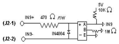
D.3 Photo isolate group 1 input format
1.The address is (Base address + 0).
2.Bit 0 represents input condition of pin 1 and pin 2 of J2 connector (J2-1 and J2-2).
3.Bit 0 to bit 7 represents input channel 1 to channel 8.
4.The input hardware configuration is
D.4 Photo isolate group 2 input format
1.The address is (Base address + 1).
2.Bit 0 represents input condition of pin 17 and pin 18 of J2 connector (J2-17 and J2-18).
3.Bit 0 to bit 7 represents input channel 9 to channel 16.
4.The input hardware configuration is
Technical
data - Isolated input Output and Relay Output
Isolated
input: The digital signal input with isolated protection.
Photo Isolator :
Word
File 4N35
Hyper
Link
Catalog |
|
| |
Manual |
| |
Device Driver
|
| |
Self Test Software
& Sample Code |
| |
Web Based DAQ
|
| |
Application
|
| |
Q&A |